Wednesday, May 24, 2023

What is torque?

Torque is a concept used in physics and engineering to describe the rotational force applied to an object around a specific axis. It is a vector quantity that represents the tendency of a force to cause rotational motion. Torque is often associated with rotating objects and is measured in units such as Newton-meters (Nm) or foot-pounds (ft-lb).

Fig 1. Torque Animation 
(link from https://upload.wikimedia.org/wikipedia/commons/0/09/Torque_animation.gif)

Key points about torque:

  1. Definition: Torque can be defined as the product of a force and the perpendicular distance from the axis of rotation to the line of action of the force. 
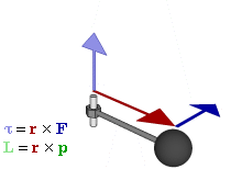
Mathematically, torque (τ) is given by the equation:

τ = r * F * sin(θ)

where τ is the torque, r is the distance from the axis of rotation to the point where the force is applied, F is the force, and θ is the angle between the force and the line connecting the axis of rotation and the point of application.

  1. Rotational Effect: Torque describes the rotational effect or turning force exerted on an object. It causes objects to rotate or change their rotational motion.
  2. Moment Arm: The distance between the axis of rotation and the point where the force is applied is known as the moment arm or lever arm. Increasing the moment arm increases the torque produced by a given force.
  3. Direction: Torque is a vector quantity and has both magnitude and direction. The direction of torque is determined by the right-hand rule. When viewed from the direction of the applied force, the thumb points in the direction of the torque.
  4. Units: Torque is typically measured in Newton-meters (Nm) or foot-pounds (ft-lb). One Newton-meter is the torque produced by a one Newton force applied at a distance of one meter from the axis of rotation.
  5. Application: Torque is essential in various applications, such as rotating machinery, engines, motors, and mechanical systems. It is used to measure and control rotational forces, determine the effectiveness of tools, and analyze the stability of objects in rotational motion.

Understanding torque is crucial in engineering fields, including mechanics, robotics, and automotive industries. It helps in designing and analyzing systems that involve rotational motion and provides insights into the behavior of rotating objects and their response to applied forces.

Learn more:

http://hyperphysics.phy-astr.gsu.edu/hbase/tord.html

https://www.thoughtco.com/calculating-torque-2698804

https://www.geeksforgeeks.org/torque/

What is speed?

Speed refers to the rate at which an object moves or covers a certain distance in a given amount of time. It is a scalar quantity that represents the magnitude of the object's velocity. Speed is typically measured in units such as meters per second (m/s), kilometers per hour (km/h), or miles per hour (mph).

Figure 1. Speed

Key points about speed:

  1. Scalar Quantity: Speed is a scalar quantity, which means it only has magnitude and does not have a specific direction associated with it. It tells us how fast an object is moving but not the direction of its motion.
  2. Calculation: Speed is calculated by dividing the distance traveled by the time taken to cover that distance. The formula for speed is:

Speed = Distance / Time

For example, if a car travels 100 kilometers in 2 hours, its speed would be 50 km/h (100 km divided by 2 hours).

  1. Instantaneous Speed vs. Average Speed: Instantaneous speed refers to the speed of an object at a specific moment in time, while average speed is the total distance traveled divided by the total time taken. Average speed gives an overall measure of how fast an object is moving over a certain period.
  2. Speed and Velocity: While speed and velocity are often used interchangeably in everyday language, they have distinct meanings in physics. Velocity is a vector quantity that includes both speed and direction. It specifies both how fast an object is moving and in which direction.
  3. Speed and Acceleration: Speed is related to acceleration, which is the rate of change of velocity. When an object accelerates, its speed changes. Positive acceleration results in an increase in speed, while negative acceleration (deceleration) leads to a decrease in speed.
  4. Speed and Motion: Speed is a fundamental concept in the study of motion and is used to describe the movement of objects in various contexts, such as in sports, transportation, and physics.

You can see the video on external resources:

  •  https://study.com/academy/lesson/measuring-the-speed-of-an-object-physics-lab.html 

It's important to note that speed alone does not provide a complete description of an object's motion. To fully understand the motion, the direction and magnitude of velocity need to be considered.


Tuesday, May 23, 2023

What is Voltage?

Voltage, also known as electric potential difference, is a fundamental concept in electricity and electrical circuits. It refers to the potential energy difference per unit charge between two points in an electric field. Voltage is measured in units called Volts (V) and is denoted by the symbol "V."

In simple terms, voltage can be thought of as the "push" or "force" that drives electric charges to move within a circuit. It represents the potential energy that an electric charge possesses due to its position in an electric field.


Fig 1. Voltage. 
Fig 2 Analogy (cite from: https://www.electricaltechnology.org/)

Key points about voltage:

  1. Potential Difference: Voltage represents the difference in electric potential between two points in a circuit. It is measured by comparing the electric potential at one point to the electric potential at another point.
  2. Electromotive Force (EMF): Voltage is often referred to as electromotive force (EMF). EMF is the energy per unit charge provided by a source, such as a battery or generator, to establish an electric potential difference in a circuit.
  3. Unit of Measurement: Voltage is measured in Volts (V). One Volt is defined as the potential difference across a conductor when a current of one Ampere flows through it, and the power dissipated is one Watt.
  4. Polarity: Voltage has polarity, which indicates the direction of the potential difference between two points. It signifies the positive and negative ends of a voltage source or the terminals of a circuit element.
  5. Voltage Sources: Voltage can be provided by various sources, including batteries, generators, power supplies, and electrical outlets. These sources create a potential difference that enables the flow of electric current in a circuit.
  6. Voltage and Current: Voltage is closely related to current in Ohm's Law. Ohm's Law states that the current flowing through a conductor is directly proportional to the voltage across it and inversely proportional to its resistance. Mathematically, Ohm's Law can be expressed as:

I = V / R

where I is the current, V is the voltage, and R is the resistance.

Voltage is a fundamental concept in understanding the behavior of electrical circuits, including the flow of electric current, power dissipation, and the operation of electronic devices. It plays a crucial role in various applications, ranging from powering electronic devices to electrical distribution systems.

External animation:

https://www.furryelephant.com/lib/img/elec-redirect.gif


6. Resistor Connections to AC Sources: Impedance, Power Dissipation, and Voltage Division

Introduction: Resistors connected to AC sources play a crucial role in electronic circuits, allowing for impedance control, power dissipation, and voltage division. Understanding how resistors interact with AC sources is essential for circuit design and analysis. In this blog post, we will delve into resistor connections to AC sources, discussing impedance, power dissipation, voltage division, and providing practical examples to solidify your understanding.

  1. Impedance in AC Circuits: In AC circuits, resistors exhibit impedance, which is the opposition to the flow of alternating current. The impedance of a resistor is purely resistive and is equal to its resistance (R).
  2. Voltage Division in AC Circuits: Similar to DC circuits, resistors connected in series to an AC source exhibit voltage division. The voltage across a resistor depends on its resistance and the total impedance in the circuit.
  3. Power Dissipation in AC Circuits: When a resistor is connected to an AC source, power is dissipated in the form of heat. The power dissipated by a resistor in an AC circuit can be calculated using the same formula as in DC circuits.

P = (Vᵣ)² / R

Where: P is the power dissipated by the resistor, Vᵣ is the voltage across the resistor, R is the resistance of the resistor.

  1. Practical Examples: Let's consider a few practical examples to illustrate resistor connections to AC sources:

Example 1: A 100 Ω resistor is connected in series to a 120 Vrms AC source with a frequency of 60 Hz.

Impedance of the resistor (Z) = R = 100 Ω

The voltage across the resistor (Vᵣ) can be calculated using Ohm's Law: Vᵣ = I * Z

Since the current (I) is the same throughout the series circuit, we can calculate it using: I = Vrms / Z

Vᵣ = (Vrms / Z) * Z Vᵣ = Vrms

Therefore, the voltage across the resistor is 120 Vrms.

Power dissipation in the resistor: P = (Vᵣ)² / R P = (120 Vrms)² / 100 Ω P ≈ 144 W

Example 2: A circuit consists of two resistors in series, R₁ = 50 Ω and R₂ = 75 Ω, connected to a 220 Vrms AC source with a frequency of 50 Hz.

Impedance of R₁ (Z₁) = R₁ = 50 Ω Impedance of R₂ (Z₂) = R₂ = 75 Ω

Voltage division across the resistors: Vᵣ₁ = (Z₁ / (Z₁ + Z₂)) * Vrms Vᵣ₁ = (50 Ω / (50 Ω + 75 Ω)) * 220 Vrms Vᵣ₁ ≈ 73.33 Vrms

Vᵣ₂ = (Z₂ / (Z₁ + Z₂)) * Vrms Vᵣ₂ = (75 Ω / (50 Ω + 75 Ω)) * 220 Vrms Vᵣ₂ ≈ 146.67 Vrms

Power dissipation in the resistors: P₁ = (Vᵣ₁)² / R₁ P₁ = (73.33 Vrms)² / 50 Ω P₁ ≈ 107.06 W

P₂ = (Vᵣ₂)² / R₂ P₂ = (146.67 Vrms)² / 75 Ω P₂ ≈ 289.39 W

Conclusion: Resistor connections to AC sources involve impedance, voltage division, and power dissipation. Understanding the concept of impedance allows you to determine the voltage across resistors in AC circuits, while power dissipation calculations help assess the heat generated by the resistors. By exploring practical examples, you can gain a deeper understanding of how resistors behave in AC circuits.


What is electron?

An electron is a subatomic particle that carries a negative electric charge. It is one of the fundamental particles that make up an atom. Electrons are found outside the atomic nucleus in regions called electron shells or energy levels.


Figure 1. Electron 

(Cited from https://www.sciencefacts.net/wp-content/uploads/2020/11/Electron-Diagram.jpg)

Key characteristics of electrons include:

  1. Charge: Electrons have a negative electric charge (-1 elementary charge). This charge is equal in magnitude but opposite in sign to the positive charge carried by protons.
  2. Mass: Electrons have a much smaller mass compared to protons and neutrons. The mass of an electron is approximately 1/1836th of the mass of a proton.
  3. Behavior: Electrons exhibit properties of both particles and waves, known as wave-particle duality. They can behave as discrete particles and also display wave-like characteristics, such as interference and diffraction.
  4. Energy Levels: Electrons occupy specific energy levels around an atomic nucleus. These energy levels, also known as electron shells or orbitals, are quantized, meaning they can only have certain discrete values.
  5. Electron Cloud: Electrons do not follow a fixed path or orbit around the nucleus. Instead, they are described by a probability distribution known as the electron cloud or electron orbital. The electron cloud represents the region where an electron is most likely to be found.
  6. Charge and Matter Interactions: Electrons play a crucial role in chemical reactions and the formation of chemical bonds. Their interactions with other atoms determine the electrical and chemical properties of substances.

Electrons are fundamental to the understanding of electricity, magnetism, and the behavior of matter at the atomic and subatomic level. They are also essential for the functioning of electronic devices and play a vital role in various fields of science, including physics, chemistry, and materials science.

External resources for learning:


What is Current?

Current, in the context of electrical circuits, refers to the flow of electric charge through a conductor. It is the rate at which electric charges, typically electrons, move past a given point in a circuit. Current is measured in units called Amperes (A) and is denoted by the symbol "I."

Fig. 1 free electrons 
cited from: https://circuitglobe.com/electric-current.html 
Fig. 2 Flow of electron
cited from: https://circuitglobe.com/electric-current.html 

In simple terms, current is the flow of electrons or charge in a closed loop circuit. It is similar to the flow of water in a pipe. Just as water flows from a higher pressure to a lower pressure, electric current flows from a region of higher electric potential (voltage) to a region of lower electric potential.

There are two types of current:

  1. Direct Current (DC): In a DC circuit, the flow of electric charge is unidirectional. The magnitude and direction of the current remain constant over time. Batteries and most electronic devices operate on DC.
  2. Alternating Current (AC): In an AC circuit, the flow of electric charge periodically changes direction. The magnitude and direction of the current vary sinusoidally with time. AC is commonly used for power distribution in homes and businesses.

Fig. 3 Analogy 
(link from https://eschooltoday.com/learn/wp-content/uploads/2020/10/explain-current-and-voltage.jpg)

The behavior of current in a circuit is governed by Ohm's Law, which states that the current (I) flowing through a conductor is directly proportional to the voltage (V) across the conductor and inversely proportional to its resistance (R). Mathematically, Ohm's Law can be expressed as:

I = V / R

where: I = Current (in Amperes) V = Voltage (in Volts) R = Resistance (in Ohms)

Current is a fundamental quantity in electrical circuits and plays a crucial role in determining the behavior and operation of various electronic components and devices.

Good external resources:


5. Resistor Connections to DC Sources: Understanding Voltage Division and Power Dissipation

Introduction: Resistors connected to DC voltage sources play a crucial role in electronic circuits, allowing for voltage control, current limitation, and power dissipation. Understanding how resistors interact with DC sources is essential for circuit design and analysis. In this blog post, we will explore resistor connections to DC sources, discuss voltage division, power dissipation, and provide practical examples to enhance your understanding.

  1. Voltage Division with Resistors: When a resistor is connected to a DC voltage source in a series circuit, voltage division occurs. The voltage across the resistor is determined by its resistance relative to the total resistance in the circuit.
  2. Voltage Division Formula: The voltage across a resistor (Vᵣ) in a series circuit connected to a DC source can be calculated using the voltage division formula:

Vᵣ = (Rᵣ / R) * V

Where: Vᵣ is the voltage across the resistor, Rᵣ is the resistance of the resistor, R is the total resistance in the circuit, V is the total voltage supplied by the DC source.

  1. Power Dissipation in Resistors: When a resistor is connected to a DC source, power is dissipated in the form of heat. The power dissipated by a resistor can be calculated using Ohm's Law or the power formula:

P = (Vᵣ)² / Rᵣ

Where: P is the power dissipated by the resistor, Vᵣ is the voltage across the resistor, Rᵣ is the resistance of the resistor.

  1. Practical Examples: Let's consider a few practical examples to illustrate resistor connections to DC sources:

Example 1: A 10 Ω resistor is connected in series with a 12 V DC source. The total resistance in the circuit is 30 Ω.

Using the voltage division formula: Vᵣ = (10 Ω / 30 Ω) * 12 V Vᵣ = (1/3) * 12 V Vᵣ = 4 V

Using the power dissipation formula: P = (4 V)² / 10 Ω P = 16 W / 10 Ω P = 1.6 W

Example 2: A circuit consists of two resistors in series, R₁ = 100 Ω and R₂ = 200 Ω, connected to a 9 V DC source.

Using the voltage division formula: Vᵣ₁ = (100 Ω / 300 Ω) * 9 V Vᵣ₁ = (1/3) * 9 V Vᵣ₁ = 3 V

Vᵣ₂ = (200 Ω / 300 Ω) * 9 V Vᵣ₂ = (2/3) * 9 V Vᵣ₂ = 6 V

Using the power dissipation formula: P₁ = (3 V)² / 100 Ω P₁ = 9 W / 100 Ω P₁ = 0.09 W

P₂ = (6 V)² / 200 Ω

P₂ = 36 W / 200 Ω P₂ = 0.18 W

Conclusion: Resistor connections to DC sources are fundamental in electronic circuits, allowing for voltage division and power dissipation. By understanding voltage division using the appropriate formula and calculating power dissipation, you can effectively analyze and design circuits involving resistors connected to DC sources. Consider the practical examples provided to solidify your understanding and apply these concepts in your circuit designs.

4. Series-Parallel Resistor Connections: Understanding Complex Circuit Configurations

Introduction: Series-parallel resistor connections are commonly encountered in complex electronic circuits, where resistors are combined in both series and parallel configurations. Analyzing such circuits requires understanding how series and parallel connections interact and affect the overall resistance. In this blog post, we will explore the concept of series-parallel resistor connections, discuss how to analyze complex circuit configurations, and provide practical examples to enhance your understanding.

  1. Series-Parallel Connections: In series-parallel resistor connections, resistors are combined using a combination of series and parallel connections within the circuit. This allows for more flexible and complex circuit designs.
  2. Analyzing Series-Parallel Configurations: To analyze a circuit with series-parallel resistor connections, follow these steps:

Step 1: Identify series and parallel sections within the circuit. Step 2: Simplify each series section by adding up the individual resistances. Step 3: Simplify each parallel section by calculating the total resistance using the reciprocal method. Step 4: Combine the simplified series and parallel sections to determine the total resistance of the circuit.

  1. Practical Examples: Let's consider a few practical examples to illustrate the analysis of series-parallel resistor connections:

Example 1: Resistor values: R₁ = 10 Ω, R₂ = 20 Ω, R₃ = 30 Ω in series, R₄ = 40 Ω, R₅ = 50 Ω in parallel

Simplifying the series section: R_series = R₁ + R₂ + R₃ = 10 Ω + 20 Ω + 30 Ω = 60 Ω Simplifying the parallel section: 1/R_parallel = 1/R₄ + 1/R₅ = 1/40 Ω + 1/50 Ω = 0.05 + 0.04 = 0.09 R_parallel = 1/0.09 Ω ≈ 11.11 Ω

Combining the series and parallel sections: R_total = R_series + R_parallel = 60 Ω + 11.11 Ω ≈ 71.11 Ω

Example 2: Resistor values: R₁ = 100 Ω, R₂ = 150 Ω in series, R₃ = 200 Ω, R₄ = 250 Ω in parallel

Simplifying the series section: R_series = R₁ + R₂ = 100 Ω + 150 Ω = 250 Ω Simplifying the parallel section: 1/R_parallel = 1/R₃ + 1/R₄ = 1/200 Ω + 1/250 Ω = 0.005 + 0.004 = 0.009 R_parallel = 1/0.009 Ω ≈ 111.11 Ω

Combining the series and parallel sections: R_total = R_series + R_parallel = 250 Ω + 111.11 Ω ≈ 361.11 Ω

  1. Applications and Implications: Series-parallel resistor connections are commonly found in various applications, such as:
  • Complex Circuits: Series-parallel connections allow for more intricate circuit designs, accommodating a wide range of electrical and electronic systems.
  • Voltage Dividers: Series-parallel configurations are utilized in voltage dividers to achieve specific voltage ratios and distribute voltage across multiple resistors.
  • Filter Networks: Series-parallel resistor configurations are used in filter circuits to achieve desired frequency responses and attenuate specific frequency components.
  • Speaker Systems: Speaker crossovers often incorporate series-parallel resistor connections to distribute power and control the frequency response of different drivers.

Conclusion: Series-parallel resistor connections are essential in complex electronic circuits, allowing for flexible design and control of resistance values. By understanding how to analyze and simplify series-parallel configurations, you can confidently tackle complex circuit designs. Consider the applications in complex circuits, voltage dividers, filter networks, and speaker systems to apply series-parallel resistor connections effectively.


3. Resistor Parallel Connections: Understanding Parallel Circuits and Calculating Total Resistance


Introduction: Resistors connected in parallel are a fundamental aspect of electronic circuits, influencing the flow of current and affecting the overall resistance. Understanding parallel connections is crucial for circuit design and analysis. In this blog post, we will explore the concept of resistors in parallel, discuss how to calculate the total resistance in a parallel circuit, and provide practical examples to enhance your understanding of parallel connections.

  1. Resistor Parallel Connections: When resistors are connected in parallel, they are arranged such that both ends of each resistor are connected to the same nodes. In parallel, the voltage across each resistor is the same, and the reciprocal of the total resistance is equal to the sum of the reciprocals of the individual resistances.
  2. Calculation of Total Resistance: To calculate the total resistance (R) in a parallel circuit, follow these steps:

    • Step 1: Identify the resistors connected in parallel. 
    • Step 2: Calculate the reciprocal of each resistance (1/R₁, 1/R₂, 1/R₃, ..., 1/R). Step 3: Sum up the reciprocals of the resistances. Step 4: Take the reciprocal of the sum to obtain the total resistance.

                    1/R = 1/R₁ + 1/R₂ + 1/R₃ + ... + 1/R R = 1/(1/R₁ + 1/R₂ + 1/R₃ + ... + 1/R)

  1. Practical Examples: Let's consider a few practical examples to illustrate parallel connections and calculate the total resistance:

    • Example 1: Resistor values: R₁ = 10 Ω, R₂ = 20 Ω, R₃ = 30 Ω

                        1/R = 1/10 Ω + 1/20 Ω + 1/30 Ω R 

                                    = 1/(0.1 + 0.05 + 0.033) Ω R 

                                   = 1/(0.183) Ω R ≈ 5.46 Ω

    • Example 2: Resistor values: R₁ = 100 Ω, R₂ = 150 Ω, R₃ = 200 Ω, R₄ = 250 Ω

                        1/R = 1/100 Ω + 1/150 Ω + 1/200 Ω + 1/250 Ω R 

                                    = 1/(0.01 + 0.0067 + 0.005 + 0.004) Ω R 

                                    = 1/(0.0257) Ω R ≈ 38.93 Ω

  1. Applications and Implications: Understanding resistor parallel connections is vital for various applications:
    • Voltage Regulation: Parallel resistor configurations are commonly used in voltage regulators to distribute the load and ensure stable voltage across multiple components.
    • Current Sharing: When resistors are connected in parallel, each resistor provides a separate path for current flow. This allows for current sharing among the resistors, ensuring an even distribution of current and preventing excessive current through any single resistor.
    • Load Balancing: In certain applications, multiple resistors are connected in parallel to balance the load across different branches of a circuit. This ensures that each resistor handles an equal portion of the total current, preventing overload and improving overall circuit performance.

Conclusion: Resistor parallel connections are essential in electronic circuits, influencing current distribution and determining the total resistance. By understanding how to calculate the total resistance in a parallel circuit and recognizing practical examples, you can confidently design and analyze circuits involving parallel resistor configurations. Consider the implications of parallel connections in voltage regulation, current sharing, load balancing, and other applications to optimize circuit performance.


2. Resistor Series Connections: Understanding Series Circuits and Calculating Total Resistance

Introduction: Resistors connected in series form an essential part of electronic circuits, influencing current flow and affecting the overall resistance. Understanding series connections is crucial for circuit design and analysis. In this blog post, we will delve into the concept of resistors in series, explore how to calculate the total resistance in a series circuit, and provide practical examples to enhance your understanding of series connections.

  1. Resistor Series Connections: When resistors are connected in series, they are placed consecutively along the same current path, sharing the same current. The voltage drop across each resistor adds up, and the total resistance is equal to the sum of individual resistances.
  2. Calculation of Total Resistance: To calculate the total resistance (R) in a series circuit, follow these steps:

    • Step 1: Identify the resistors connected in series. 
    • Step 2: Add up the individual resistances (R₁, R₂, R₃, ..., R).

                    R = R₁ + R₂ + R₃ + ... + R

  1. Practical Examples: Let's consider a few practical examples to illustrate series connections and calculate the total resistance:
    •   Example 1: Resistor values: R₁ = 10 Ω, R₂ = 20 Ω, R₃ = 30 Ω

                        R = 10 Ω + 20 Ω + 30 Ω R = 60 

    • Example 2: Resistor values: R₁ = 100 Ω, R₂ = 150 Ω, R₃ = 200 Ω, R₄ = 250 Ω

                        R = 100 Ω + 150 Ω + 200 Ω + 250 Ω R = 700 Ω

  1. Applications and Implications: Understanding resistor series connections is vital for various applications:
    • Voltage Dividers: Series resistor configurations are commonly used in voltage dividers, where the output voltage is a fraction of the input voltage. The relative values of resistors determine the voltage division ratio.
    • Current Limiting: By connecting a series resistor with a load, the current flowing through the load can be controlled and limited, preventing excessive current flow.
    • LED Circuits: Series resistors are often employed in LED circuits to limit the current and protect the LED from excessive current flow, ensuring proper operation and longevity.

Conclusion: Resistor series connections are essential in electronic circuits, influencing current flow and determining total resistance. By understanding how to calculate the total resistance in a series circuit and recognizing practical examples, you can confidently design and analyze circuits involving series resistor configurations. Remember to consider the implications of series connections in voltage dividers, current limiting, and LED circuits, among others, for effective circuit design.


1. Demystifying Resistors: Understanding the Basics and Applications

Introduction: Resistors are fundamental components in electronic circuits that play a crucial role in controlling current flow and limiting voltage. Understanding resistors is essential for anyone interested in electronics or circuit design. In this blog post, we will dive into the world of resistors, exploring their basic principles, different types, and applications in electronic circuits. By the end of this guide, you will have a solid understanding of resistors and how they are used in various electrical and electronic systems.

  1. What is a Resistor? A resistor is a passive two-terminal electronic component that opposes the flow of electric current. It is designed to have a specific resistance value, typically measured in ohms (Ω). Resistors are made from materials with high resistivity, such as carbon composition, metal film, or wire-wound materials.
  2. Types of Resistors (see Table 1): There are various types of resistors available, each suited for specific applications:
    • Carbon Composition Resistors: These are among the oldest and most common types of resistors. They consist of a carbon-filled ceramic core with wire leads. Carbon composition resistors are known for their reliability and stability but have higher tolerances compared to other types.
    • Metal Film Resistors: Metal film resistors are made by depositing a thin metal film onto a ceramic substrate. They provide better accuracy, lower noise, and tighter tolerances compared to carbon composition resistors. Metal film resistors are widely used in precision applications.
    • Wire-Wound Resistors: Wire-wound resistors are constructed by winding a resistive wire around an insulating core. They offer high power handling capabilities and low temperature coefficients. Wire-wound resistors are commonly used in power applications and where high precision is required.
    • Surface Mount Resistors: Surface mount resistors (SMD) are compact resistors designed for surface mount technology. They are available in various package sizes and are widely used in modern electronic devices and printed circuit boards (PCBs).

Table 1. Type of Resistors

Resistor Type

Description

Commercial Example

Carbon Composition

Made of carbon-filled ceramic core with wire leads

Allen-Bradley Carbon Comp

Metal Film

Thin metal film deposited onto a ceramic substrate

Vishay Dale Metal Film

Wire-Wound

Resistive wire wound around an insulating core

Ohmite Little Demon

Surface Mount (SMD)

Compact resistors designed for surface mount technology

Panasonic ERJ Series


  1. Applications of Resistors: Resistors find applications in a wide range of electronic circuits and systems. Some common applications include:
    • Voltage Division: Resistors are used in voltage dividers to divide voltage in a circuit. By connecting resistors in series or parallel, specific voltage ratios can be achieved, which is useful for level shifting, biasing, and sensor interfacing.
    • Current Limiting: Resistors are often used to limit current flow in a circuit. By connecting a resistor in series with a load, the current passing through the load can be controlled to prevent damage or achieve desired operating conditions.
    • Current Sensing: Resistors can be employed as current sensing elements in circuits. By measuring the voltage drop across a known resistor value, the current flowing through a specific section of a circuit can be determined.
    • Signal Conditioning: Resistors play a vital role in signal conditioning circuits, such as filtering, attenuating, and impedance matching. They help shape and modify electrical signals to meet the requirements of subsequent stages in a circuit.

Conclusion: Resistors are fundamental components in electronics, controlling current flow, limiting voltage, and playing various roles in electronic circuits. Understanding the basics of resistors, their types, and applications is essential for anyone involved in electronics, circuit design, or troubleshooting. By grasping the concepts discussed in this guide, you are well on your way to confidently incorporating resistors into your electronic projects and circuits.


Power Electronics Transforming Healthcare: Emerging Trends in Wearable Devices and Self-Powered Healthcare Systems

Explore the transformative role of power electronics in healthcare systems. Discover the emerging trends in wearable devices, self-powered healthcare systems, and how power electronics advancements are revolutionizing patient monitoring, diagnostics, and improving healthcare outcomes.

Introduction: Power electronics is playing a vital role in revolutionizing the healthcare industry, enabling innovative solutions in patient monitoring, diagnostics, and self-powered healthcare systems. The emergence of wearable devices and self-powered technologies is transforming the way healthcare is delivered, offering personalized and continuous monitoring while enhancing patient convenience. In this blog post, we will explore the emerging trends in power electronics within the healthcare sector, focusing on wearable devices and self-powered healthcare systems. Let's delve into the future of healthcare with power electronics.

  1. Wearable Devices: Wearable devices powered by power electronics are reshaping healthcare delivery and patient monitoring:
    • Continuous Health Monitoring: Wearable devices equipped with sensors, biofeedback systems, and power electronics enable continuous monitoring of vital signs, activity levels, sleep patterns, and more. These devices provide valuable real-time data for healthcare professionals, facilitating personalized care and early intervention.
    • Remote Patient Monitoring: Power electronics-integrated wearable devices offer remote patient monitoring capabilities, allowing healthcare providers to track patients' health conditions and receive alerts on critical changes. This enables proactive healthcare management, reduces hospital visits, and improves patient outcomes.
    • Drug Delivery and Therapy: Wearable devices can incorporate power electronics-driven drug delivery systems, providing precise and controlled administration of medications or therapies. This enhances treatment efficacy, patient compliance, and the overall management of chronic conditions.
  1. Self-Powered Healthcare Systems: Power electronics advancements enable the development of self-powered healthcare systems, reducing reliance on external power sources:
    • Energy Harvesting: Self-powered healthcare systems utilize energy harvesting techniques, such as solar cells, thermoelectric generators, or motion-based generators. Power electronics technology optimizes energy conversion and management, powering sensors, devices, and communication modules without the need for batteries or external power sources.
    • Implantable Medical Devices: Power electronics-driven self-powered systems are essential for implantable medical devices. These devices harvest energy from the body's physiological processes, such as body heat, motion, or biofluids, to power sensors, actuators, and wireless communication modules. This eliminates the need for invasive battery replacement surgeries and enhances patient comfort and safety.
  1. Improved Healthcare Accessibility and Personalized Care: Power electronics advancements contribute to improved healthcare accessibility and personalized care:
    • Point-of-Care Diagnostics: Portable and power electronics-enabled diagnostic devices offer on-the-spot testing and analysis, reducing the need for laboratory visits and enabling faster diagnosis and treatment decisions. This is particularly beneficial in resource-limited settings and remote areas.
    • Telemedicine and Remote Care: Power electronics technology facilitates telemedicine and remote care solutions. Wearable devices, coupled with power electronics-enabled communication systems, allow healthcare providers to remotely monitor patients, conduct virtual consultations, and offer personalized care from a distance.

Conclusion: The integration of power electronics in healthcare systems is driving significant advancements in wearable devices, self-powered technologies, and personalized care. Wearable devices powered by power electronics provide continuous monitoring, remote patient management, and improved drug delivery. Self-powered healthcare systems eliminate the need for external power sources, enabling implantable devices and energy-efficient diagnostics. As power electronics continues to evolve in the healthcare sector, we can anticipate enhanced healthcare accessibility, improved patient outcomes, and a more personalized and efficient healthcare experience.


Cutting the Cord: Exploring Emerging Trends in Power Electronics with Wireless Power Transfer

Introduction: In a world increasingly driven by wireless connectivity, the concept of wireless power transfer has emerged as a groundbreaking trend in power electronics. The ability to transmit power without the need for physical connections opens up new possibilities for convenient charging and power delivery. In this blog post, we will explore the emerging trend of wireless power transfer in power electronics, highlighting its advantages, applications, and the transformative impact it may have on various industries. Let's delve into the future of power electronics with wireless power transfer.

  1. Convenience and Flexibility: Wireless power transfer offers unprecedented convenience and flexibility in charging and powering devices:
    • Cordless Charging: With wireless power transfer, there's no need for cables or physical connections to charge devices. Simply placing a compatible device on a charging pad or within the range of a wireless charging system enables convenient and effortless charging.
    • Mobility and Flexibility: Wireless power transfer allows for greater mobility and flexibility, as devices can be charged or powered while in use or on the move. This is particularly advantageous in applications such as electric vehicles, medical devices, and IoT devices, where physical connections may be impractical or inconvenient.
  1. Efficiency and Safety: Wireless power transfer technology focuses on improving energy efficiency and ensuring safety:
    • Energy Transfer Efficiency: Power electronics plays a crucial role in optimizing energy transfer efficiency in wireless charging systems. Through advanced circuit design, power conversion techniques, and control algorithms, power electronics minimizes energy losses and maximizes the efficiency of wireless power transfer.
    • Foreign Object Detection: Power electronics-enabled wireless charging systems incorporate safety mechanisms such as foreign object detection. These systems can detect and prevent energy transfer when foreign objects, such as metal items, are placed on the charging pad, ensuring safe and reliable operation.
  1. Applications and Industries: Wireless power transfer has the potential to transform various industries and applications:
    • Consumer Electronics: Wireless charging technology is increasingly being integrated into smartphones, smartwatches, and other portable devices. Power electronics-enabled wireless charging pads and platforms offer convenience and a clutter-free charging experience for consumers.
    • Automotive Industry: Wireless power transfer holds great promise for electric vehicles (EVs) and autonomous driving. By integrating wireless charging systems into roads or parking areas, EVs can charge wirelessly while driving or parked, eliminating the need for manual charging connections and extending the range and usability of EVs.
    • Medical Devices: Power electronics-driven wireless power transfer technology is revolutionizing the healthcare industry. Implantable medical devices, such as pacemakers and neurostimulators, can be powered wirelessly, eliminating the need for invasive surgeries to replace batteries.

Conclusion: The emergence of wireless power transfer technology in power electronics brings us closer to a future where convenient and efficient wireless energy transmission is a reality. The advantages of convenience, flexibility, efficiency, and safety make wireless power transfer an exciting trend with vast potential. As power electronics continues to advance in this field, we can anticipate the widespread integration of wireless power transfer in consumer electronics, automotive applications, medical devices, and beyond, transforming the way we charge and power our devices.


Powering the Future: Emerging Trends in Power Electronics with Energy Storage Systems

Introduction: As the demand for clean energy and energy storage grows, power electronics technology is playing a pivotal role in advancing energy storage systems. The integration of power electronics with energy storage systems, including batteries and supercapacitors, has opened up new avenues for renewable energy integration, grid stability, and efficient energy management. In this blog post, we will explore the emerging trends in power electronics with energy storage systems, highlighting their advantages, applications, and the transformative impact they bring to various sectors. Let's dive into the future of power electronics in energy storage.

  1. Renewable Energy Integration: Energy storage systems coupled with power electronics facilitate the effective integration of renewable energy sources into the grid:
    • Grid Stabilization: Power electronics enable the efficient management of energy flows between renewable energy sources and the grid. By regulating voltage and frequency fluctuations, power electronics help stabilize the grid, ensuring a smooth and reliable integration of intermittent renewable energy generation.
    • Time Shifting and Peak Load Management: Energy storage systems combined with power electronics allow for time shifting of energy, storing excess energy during low demand periods and releasing it during peak load periods. This load management strategy reduces strain on the grid, enhances system reliability, and optimizes energy usage.
  1. Microgrid and Off-grid Applications: Power electronics-integrated energy storage systems offer significant advantages for microgrid and off-grid applications:
    • Energy Independence: Energy storage systems provide a reliable and decentralized source of power for microgrids and off-grid systems. Power electronics enable seamless integration, control, and management of energy storage, ensuring a stable and continuous power supply.
    • Demand Response: By leveraging power electronics technology, energy storage systems enable effective demand response strategies in microgrid environments. Power electronics facilitate load control, peak shaving, and load balancing, allowing microgrids to adjust energy consumption based on demand and grid conditions.
  1. Electric Vehicle Charging Infrastructure: Power electronics plays a vital role in the development of electric vehicle (EV) charging infrastructure, utilizing energy storage systems:
    • Fast Charging: Power electronics technology combined with energy storage systems allows for high-power fast charging of electric vehicles. By efficiently managing power flow, power electronics optimizes the charging process, reducing charging time and enhancing EV usability and convenience.
    • Grid Integration and Vehicle-to-Grid (V2G) Applications: Power electronics-integrated energy storage systems enable bidirectional power flow, facilitating vehicle-to-grid (V2G) applications. This technology allows EVs to supply power back to the grid during peak demand periods or in emergency situations, contributing to grid stability and energy management.

Conclusion: The integration of power electronics with energy storage systems represents a significant trend in the energy sector, offering numerous advantages such as renewable energy integration, grid stability, and enhanced efficiency. By harnessing the power of power electronics, energy storage systems are revolutionizing renewable energy utilization, microgrid applications, and electric vehicle charging infrastructure. As power electronics technology continues to evolve, we can expect further advancements in energy storage systems, fostering a more sustainable and resilient energy future.


Powering the Connected Future: Emerging Trends in Power Electronics with IoT and Smart Grids

Introduction: The convergence of power electronics, Internet of Things (IoT), and smart grid technologies is paving the way for a connected and sustainable energy ecosystem. By integrating power electronics with IoT and smart grids, we can achieve real-time monitoring, intelligent energy management, and efficient utilization of energy resources. In this blog post, we will explore the emerging trends in power electronics with IoT and smart grids, highlighting their advantages, applications, and the transformative impact on energy systems. Let's delve into the future of power electronics in the era of IoT and smart grids.

  1. Real-time Monitoring and Control: The integration of power electronics with IoT enables real-time monitoring and control of energy systems:
    • Smart Meters and Sensors: IoT-enabled smart meters and sensors provide detailed information on energy consumption, generation, and grid conditions. Power electronics devices, such as communication interfaces and data acquisition systems, facilitate seamless connectivity and data exchange between smart meters, sensors, and energy management systems.
    • Remote Monitoring and Control: Power electronics-based remote monitoring and control systems allow energy system operators to remotely manage and optimize energy usage. Real-time data from IoT devices combined with power electronics technology enables proactive decision-making, load balancing, and demand response strategies for efficient energy management.
  1. Demand Response and Energy Flexibility: The combination of power electronics, IoT, and smart grids enables demand response and energy flexibility:
    • Demand Response Programs: Power electronics-based systems integrate with IoT devices to enable demand response programs. By adjusting energy usage based on grid conditions and price signals, power electronics optimizes energy consumption, reduces peak demand, and supports grid stability. This helps balance energy supply and demand, reduce energy costs, and enhance grid efficiency.
    • Energy Flexibility and Load Management: Power electronics devices, in combination with IoT-enabled smart appliances and energy management systems, allow for dynamic load management and energy flexibility. By intelligently controlling and optimizing energy usage based on user preferences, grid conditions, and renewable energy availability, power electronics promotes efficient utilization of energy resources and supports the integration of renewable energy into the grid.
  1. Grid Efficiency and Resilience: IoT and smart grid integration with power electronics technology improve grid efficiency and resilience:
    • Grid Monitoring and Optimization: IoT devices and power electronics-based grid monitoring systems enable real-time grid monitoring, fault detection, and optimization. This helps identify and address issues promptly, optimize power flow, and ensure reliable and efficient grid operation.
    • Power Quality and Grid Stability: Power electronics devices play a crucial role in maintaining power quality and grid stability. By incorporating advanced control algorithms and voltage regulation capabilities, power electronics devices improve grid performance, reduce voltage fluctuations, and mitigate power quality issues.

Conclusion: The integration of power electronics, IoT, and smart grids represents a transformative trend in the energy sector. By harnessing the power of real-time monitoring, demand response, and grid optimization, this integration enables efficient energy management, enhances grid efficiency, and promotes a more sustainable and interconnected energy ecosystem. As power electronics continues to evolve in the era of IoT and smart grids, we can expect further advancements in energy efficiency, grid resilience, and the realization of a smarter and greener future.


Powering the Future: Emerging Trends in Power Electronics with Wide-Bandgap Semiconductor Materials

Introduction: Power electronics technology is continuously evolving, and the adoption of wide-bandgap semiconductor materials has emerged as a game-changer. Silicon Carbide (SiC) and Gallium Nitride (GaN) are revolutionizing power electronics by offering superior properties over traditional silicon-based devices. In this blog post, we will explore the emerging trends in power electronics with wide-bandgap semiconductor materials, highlighting their advantages, applications, and the potential impact on various industries. Let's dive into the future of power electronics with SiC and GaN.

  1. Higher Efficiency and Power Density: Wide-bandgap semiconductor materials, such as SiC and GaN, exhibit unique properties that enable higher efficiency and power density in power electronics:
    • SiC Devices: Silicon Carbide devices have lower switching losses, reduced conduction losses, and higher temperature tolerance compared to traditional silicon devices. This results in higher energy efficiency, reduced heat dissipation, and improved overall system performance.
    • GaN Devices: Gallium Nitride devices offer faster switching speeds, lower on-resistance, and higher breakdown voltage capabilities. These properties enable higher frequency operation, compact designs, and improved power density. GaN devices are particularly suitable for applications that require high-speed switching and high-frequency operation.
  1. Compact Designs and Lightweight Systems: The utilization of wide-bandgap semiconductor materials in power electronics contributes to compact and lightweight system designs:
    • SiC and GaN Power Modules: SiC and GaN devices allow for higher power densities, enabling the development of smaller and more compact power modules. These modules require fewer components, occupy less space, and contribute to the miniaturization of power electronic systems.
    • High-Frequency Operation: The high switching speeds and low losses of wide-bandgap semiconductor devices facilitate high-frequency operation. This, in turn, enables the design of smaller passive components such as inductors and capacitors, resulting in more compact and lightweight power electronic systems.
  1. Emerging Applications and Industries: The adoption of SiC and GaN in power electronics opens up new possibilities and applications across various industries:
    • Electric Vehicles (EVs): SiC and GaN devices are increasingly being used in EV powertrain systems, enabling higher efficiency, longer range, and faster charging. These advanced materials help optimize power conversion and motor control, contributing to the widespread adoption of electric vehicles.
    • Renewable Energy: SiC and GaN devices play a vital role in optimizing power conversion and energy management in renewable energy systems, such as solar inverters and wind turbine converters. The higher efficiency and improved thermal performance offered by these materials enhance the overall performance and reliability of renewable energy systems.
    • Aerospace and Defense: Wide-bandgap semiconductor devices find applications in aerospace and defense systems, where high power density, lightweight designs, and high reliability are crucial. SiC and GaN devices enable efficient power conversion, reduced weight, and enhanced performance in aircraft power systems, radar systems, and electronic warfare applications.

Conclusion: The emergence of wide-bandgap semiconductor materials, such as SiC and GaN, marks a significant advancement in power electronics technology. These materials offer higher efficiency, compact designs, and improved performance, paving the way for a more sustainable and energy-efficient future. As the adoption of SiC and GaN continues to grow, we can expect further advancements in power electronics across industries such as electric


Powering Sustainability: Advantages of Power Electronics in Reducing Environmental Impact

Introduction: In the face of global environmental challenges, it has become imperative to adopt technologies that minimize our impact on the planet. Power electronics technology offers a range of advantages that contribute to reducing environmental impact and promoting sustainability. By enabling energy efficiency, facilitating renewable energy integration, and promoting sustainable practices, power electronics plays a vital role in driving a greener future. In this blog post, we will explore the advantages of power electronics in reducing environmental impact and fostering sustainability across various sectors.

  1. Energy Efficiency and Conservation: Power electronics technology plays a key role in improving energy efficiency and conservation, leading to reduced environmental footprint:
    • Efficient Power Conversion: Power electronics devices, such as converters and inverters, optimize the conversion of electrical power, minimizing energy losses during transmission and distribution. By improving power conversion efficiency, power electronics reduces overall energy consumption and carbon emissions.
    • Load Management and Control: Power electronics-based control systems enable intelligent load management, regulating power consumption based on demand. By optimizing power usage, power electronics reduces energy wastage and promotes efficient utilization of resources.
    • Standby Power Reduction: Power electronics technology incorporates standby power reduction techniques, ensuring that devices consume minimal power when not in active use. This reduces energy waste and contributes to energy efficiency in homes, offices, and industries.
  1. Renewable Energy Integration: Power electronics is instrumental in integrating renewable energy sources, leading to a cleaner and more sustainable energy mix:
    • Grid Integration: Power electronics devices, such as grid-tied inverters, facilitate the seamless integration of renewable energy sources, such as solar and wind, into the existing power grid. By converting and synchronizing renewable energy with the grid, power electronics enables the efficient utilization of clean energy resources.
    • Renewable Energy Optimization: Power electronics technology optimizes the performance of renewable energy systems, maximizing power extraction and output. This ensures that renewable energy sources operate at their highest efficiency, reducing reliance on fossil fuels and minimizing greenhouse gas emissions.
  1. Sustainable Practices and Resource Conservation: Power electronics promotes sustainable practices and resource conservation across various domains:
    • Smart Grid Technology: Power electronics technology enables the implementation of smart grid systems, promoting efficient energy distribution, load management, and demand response. By optimizing energy usage and reducing grid losses, power electronics contributes to sustainable grid operation.
    • Electric Vehicle Charging Infrastructure: Power electronics plays a critical role in the development of electric vehicle (EV) charging infrastructure. By efficiently managing power flow, power electronics enables faster and more efficient charging of EVs, reducing reliance on fossil fuels and promoting cleaner transportation.
    • Industrial Applications: Power electronics-based systems and controls enable energy-efficient operation in industries, reducing energy consumption and environmental impact. This includes applications such as motor drives, lighting systems, and power management in industrial processes.

Conclusion: The advantages of power electronics in reducing environmental impact are significant, ranging from improved energy efficiency to renewable energy integration and sustainable practices. By promoting energy conservation, facilitating the integration of renewable energy, and fostering sustainable practices, power electronics technology paves the way for a greener and more sustainable future. As we continue to embrace power electronics innovations, we move closer to achieving a more environmentally conscious and sustainable society.

Unleashing the Potential: Advantages of Power Electronics in Enhancing System Performance and Reliability

Introduction: Power electronics technology has emerged as a cornerstone in enhancing system performance and reliability across a wide range of applications. By offering precise control, efficient power management, and fault protection, power electronics revolutionizes the way systems operate, ensuring optimal performance and durability. In this blog post, we will delve into the advantages of power electronics, highlighting its role in elevating system performance and reliability in diverse industries.

  1. Precise Power Control and Regulation: One of the key advantages of power electronics is its ability to provide precise control and regulation of power, leading to improved system performance:
    • Voltage and Current Regulation: Power electronics devices, such as voltage regulators and current controllers, enable accurate control of power parameters. This ensures that systems receive stable and consistent power, preventing voltage or current fluctuations that could adversely impact performance or damage sensitive components.
    • Dynamic Response: Power electronics-based control systems offer high-speed and dynamic response capabilities, allowing systems to quickly adapt to changes in operating conditions. This ensures stable and reliable operation even under varying load conditions, maximizing system performance.
  1. Efficient Power Management: Power electronics technology enables efficient power management, optimizing energy utilization and enhancing system performance:
    • Energy Conversion Efficiency: Power electronics devices, such as converters and inverters, facilitate efficient energy conversion between different forms, minimizing energy losses during the process. This leads to higher overall energy efficiency, reducing waste and enabling more sustainable operation.
    • Power Quality Improvement: Power electronics-based systems improve power quality by addressing issues such as harmonic distortion, power factor correction, and voltage regulation. Enhanced power quality ensures that systems receive clean and reliable power, mitigating the risk of disturbances and improving system performance and longevity.
  1. Fault Protection and Robust Operation: Power electronics plays a critical role in safeguarding systems against faults and ensuring robust operation:
    • Fault Detection and Isolation: Power electronics devices incorporate fault detection and isolation mechanisms, allowing for quick identification and isolation of faults. By promptly responding to faults, power electronics systems protect system components, prevent damage, and minimize downtime.
    • Overload and Short-Circuit Protection: Power electronics-based protection circuits, such as current limiters and overload detectors, safeguard systems against excessive current and short-circuit conditions. These protective measures prevent equipment damage and ensure the reliable and continuous operation of systems.
    • Thermal Management: Power electronics technology enables efficient thermal management through temperature monitoring and control. This prevents overheating and thermal stress, enhancing system reliability and extending the lifespan of components.

Conclusion: The advantages of power electronics in enhancing system performance and reliability are significant. Through precise power control, efficient power management, and fault protection, power electronics technology optimizes the operation of various systems, ensuring optimal performance and robustness. As power electronics continues to advance, we can expect further improvements in system efficiency, reliability, and longevity, driving innovation across industries.